Introduction
Magnetism is a property of the material. A magnetic object will emit a magnetic field, which is very similar to and often confused with the electrical field. Just like electrical field lines, magnetic fields can be represented by magnetic field lines. Magnetic field lines surrounding a magnet will always form closed loops. Magnetic field lines will always travel from the North pole to the South pole.
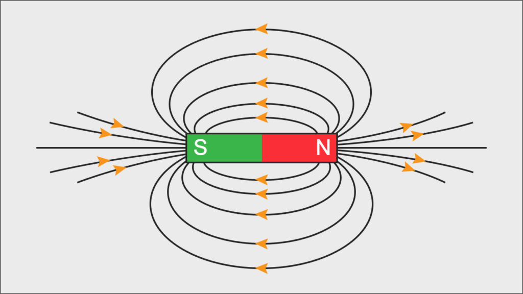
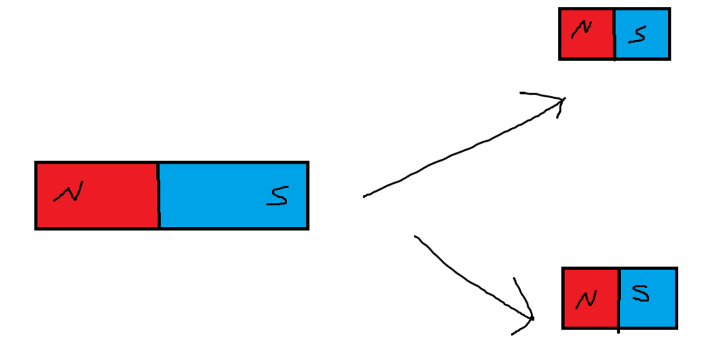
All magnetic fields will always have a North and South pole. In other words, there are no monopole magnets. There are no only North or only South magnets. If you took a magnet and cut it down the middle, you would get two different magnets, each with their own respective North and South.
The strength of a magnetic field is measured in Tesla, which has the units of Newtons per meter. A one tesla magnetic field will exert 1 N for every meter it has 1 Amp of current. One tesla is a lot, and most magnetic fields have to be measured many magnitudes smaller.
One of the most important concepts of magnetism links it with the study of electricity (electromagnetism). Any electric current will produce a magnetic field. If you have a current-carrying wire, the magnetic field will loop around the wire.

The direction in which the magnetic field curls around the wire (clockwise or counterclockwise) has to be determined using the right-hand rule. Below is a video tutorial with the right-hand rule.
(I did not create the video): https://www.youtube.com/watch?v=LAnRTNwrFMo
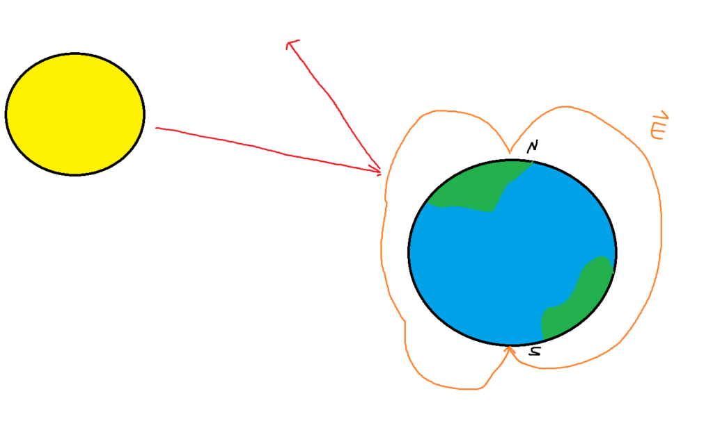
We know that a current-carrying wire will produce an electric field, but a magnetic field can also exert a force on a current-carrying wire. That phenomenon is the reason why the magnetic field of the Earth is able to deflect radiation.
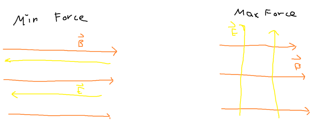
The force from a magnetic field on a current-carrying wire will always be perpendicular to both the magnetic field and the current. Mathematically, the direction of the force can be figured out by doing the cross product between the two. There exists another right-hand rule that goes as follows:
(The video is not mine): https://www.youtube.com/watch?v=dFT7-s0jh0
The equation for the magnitude of a magnetic force from a current carrying wire is as follows:

I – Current (Amps), L – Length of Wire (meters), B – Seperation Vector (meters)
Theta is the angle between the current and the magnetic field. If the magnetic field is perpendicular to the current, then the force will be maximized. If the magnetic field is parallel, then no force is exerted at all.
We can redefine the above equation. Current can be defined as the number of electrons that pass through a certain area over some period of time. If we assume a single charge, the current is simply the charge of the particle over time. The length variables can also be reinterpreted as velocity by time. Applying all of the substitutions, we get the following:

An important takeaway from the readjusted formula is that the force gets stronger the faster a particle is moving.
Ampere’s Law
Ampere discovered that two wires carrying current in the same direction will attract each other and that two wires carrying current in the opposite direction will repel each other.

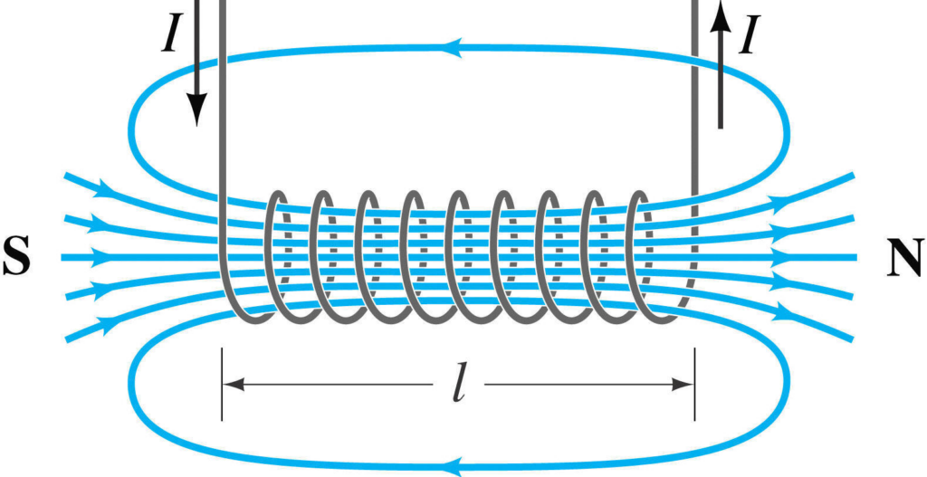
The interactions between current-carrying wires led to the solenoid-shaped wire. A solenoid is basically just a wire that has been curled multiple times into a cylinder shape.
The solenoid will produce a strong magnetic field on the inside with both the North pole and the South pole.
Another product of the interactions between current-carrying wires was the electrical motor. Ampere figured out that if you looped a wire and passed a current through it, the contraption would spin. The left and right sides of the loop are exerting a magnetic force, causing each other to move around.

He also observed that magnetic fields seemed to get weaker the farther you were from them.
Ampere was crucial to the development of electromagnetism, but his most important contribution was Ampere’s Law (which applies as long as the current is constant). Ampere’s law goes as follows:

Ampere’s law states that the strength of the magnetic field along the perimeter of a closed loop (obtained through a line integral) is proportional to the current that is enclosed in that closed loop.
Below is an example of finding the strength of the magnetic field around a current-carrying wire. In our system, there is only one object with current, which is the wire, so we can create a circle (a form of closed path). If we make the circle the exact radius of the wire, we are guaranteed to enclose all of the current in the system. By that definition, the enclosed current is simply equal to the current of the wire.
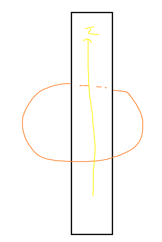
For more advanced shapes, we would have to do a line integral around the closed path, but luckily magnetic fields emit force uniformly, and the line integral of a circle is a pretty well-known fact (circumference formula). Integrating and rearranging will get us the following:

For the strength of the magnetic field created by a solenoid, almost all of strength is concentrated in the middle. The strength of the magnetic field on the inside of the solenoid is approximated as follows (where n represents the number of loops):

Solenoids are primarily used in electrical motors. A current-carrying wire is capable of creating torque through its own magnetism, but having a solenoid that exerts vast amounts of force is ideal.
The magnetic fields will only affect those that are perpendicular to them (remember the equation from earlier). For an optimal setup, the solenoid will affect the left and right sides of the loop, causing movement in opposite directions and creating a spinning motion.
In a similar fashion to electrical fields, two different magnetic fields can also be summed together to produce a single magnetic field (superposition). This means that two magnetic fields going in opposite directions will cancel each other out, and two magnetic fields going in the same direction will reinforce each other.
Induction and Faraday’s Law
Induction is one of the strange properties of electromagnetism that kind of just occurs. Regardless of this fact, induction is crucial to the use of electricity in real-life applications. The question that Faraday asked was, is it possible for magnetic fields to create an electrical charge much like how electrical currents can create magnetic fields?
Faraday’s Law of Induction states that only a changing magnetic field will induce an electromotive force (EMF) in a wire. An electromotive force is what causes electrons to move (and thus a current to form).
This means that if you put a magnet next to a wire, nothing will happen. However, if you start waving around the magnet, then an EMF will be induced. That is because the magnetic field is now changing; depending on where you move it, the magnetic force may be stronger or weaker. The strength of the magnetic field changes because of changes in angle and distance. Instead of moving the magnet, you could also move the wire itself and get similar results. Increasing the amount of wire you have will also induce an EMF since there are more places for the magnetic field to act. The faster the magnetic field changes, the more EMF is generated.
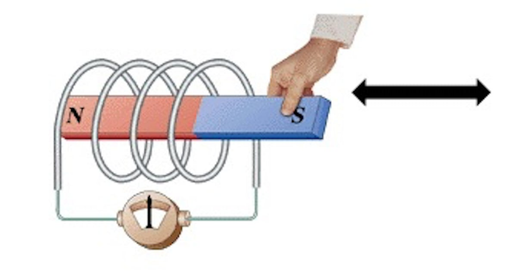
An important measure for studying induction is magnetic flux, which is equal to the “amount” of magnetic field running through a wire. The units of magnetic flux are webers (Tesla * meters squared). The magnetic flux is defined as the following:

Theta represents the angle between the magnetic field being studied and the line perpendicular to the face of the wire. That means that magnetic flux is maximized the more perpendicular it is to the wire. Magnetic flux creates a more compact way to define the strength of an induced current. It turns out that what really matters for the strength of EMF is the rate of change of the magnetic flux.
Faraday’s Law predicts the formation of a current due to a change in a magnetic field, but what direction is the current flowing in?
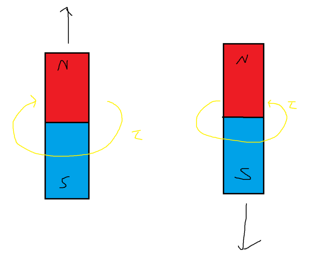
Lenz’s law states that the direction induced is opposite to the change in magnetic flux. It’s probably best to use an example. Below is an image of the direction of current in a loop of wire as a magnet moves up and down through it.
Power
Energy is never created or destroyed; it is only transformed into a different form. That means we are able to convert electrical energy into mechanical energy and vice versa. Electric motors take electrical energy and turn it into mechanical power. Electric generators turn mechanical energy into electrical energy. Our ability to convert mechanical energy into electrical energy relies on induction.
Electrical generators are basically just a loop of wire in between two magnets. The loop of wire uses a handle or some other contraption so it can be turned (this is the mechanical energy part). While the fan is spinning, it changes angle, causing a change in the interactions with the two magnets on either side. Then, the changing effects of the magnetic field cause an induced current in the loop of wire (electrical energy).
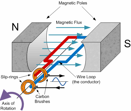
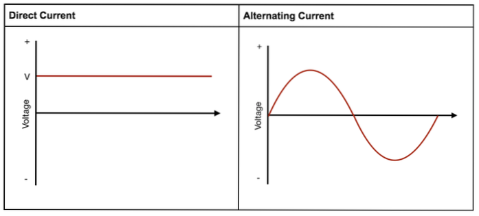
We created an electrical current, but one question still remains. What direction does the induced current in the wire go? If you applied Lenz’s law to the rotating loop of wire, you would figure out that the current would flip-flop direction. A current that oscillates is called an alternating current (AC current). Most of the time, we have been dealing with direct current (DC), which is current that only flows in one direction.
The graph of time vs. current of an alternating current t is a continuous sinusoidal graph. It is not discrete, like direct current. Unlike DC, AC will not always be at its maximum potential. There are times when the system is outputting maximum current and other times when it is outputting no current at all.
Although alternating current might sound worse than directional current, its oscillatory nature gives it some significant properties. We know that any current-carrying wire produces a magnetic field. We also know that the strength of that magnetic field relies on the current, which is constantly changing since it is alternating. Finally, we know that a change in the strength of the magnetic field can invoke a current. That means a wire carrying AC current can induce current in other nearby wires.
When it comes to transmitting electricity over long distances, efficiency becomes a problem. A lot of power will be lost as heat energy. If you write out the equation for electrical power and substitute V with I*R (through Ohm’s law), you get the following:

Based on the equation, engineers wanted to minimize the current since it has a greater effect on the total energy loss of the system. However, they couldn’t just lower the current since many electrical products require a certain amount of current to work. They needed a way to convert between high and low currents. A way to transport low current and then turn it into high current.
The problem led to the development of the transformer, which is able to convert between high and low current. The most basic transformer consists of two inductors (a wire with a lot of loops). The schematic might look something like the following:
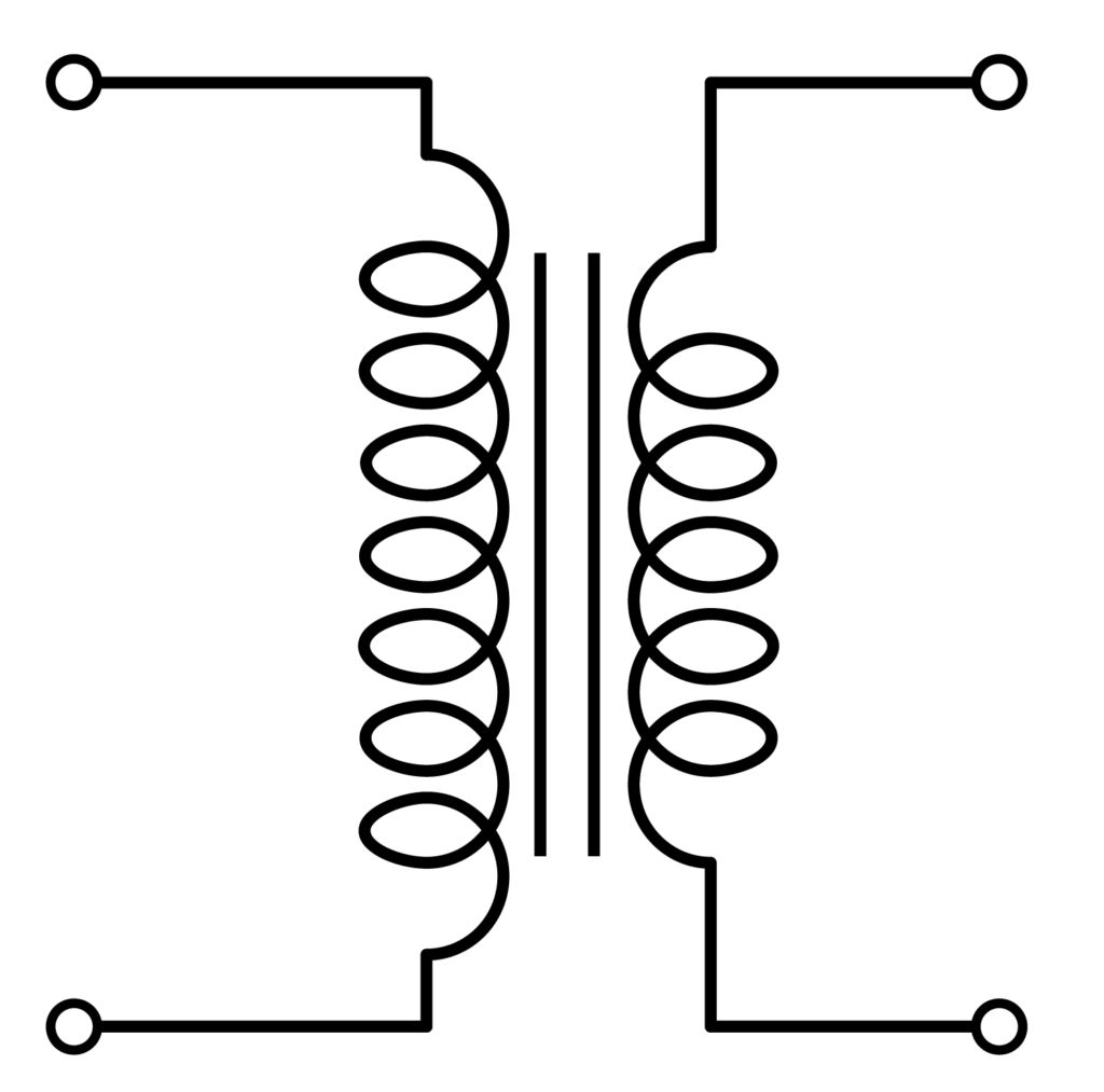
If you run an alternating current through one of the inductors it will induce a current flowing in the opposite direction (due to Lenz’s law) in the other inductor (this is called mutual inductance). An inductor is just a giant coil of wires and how well it induces current / receives induced current depends on the amount of loops it has. More coils means a strong magnetic field force making it the strength of induced currents it gives / receives stronger.

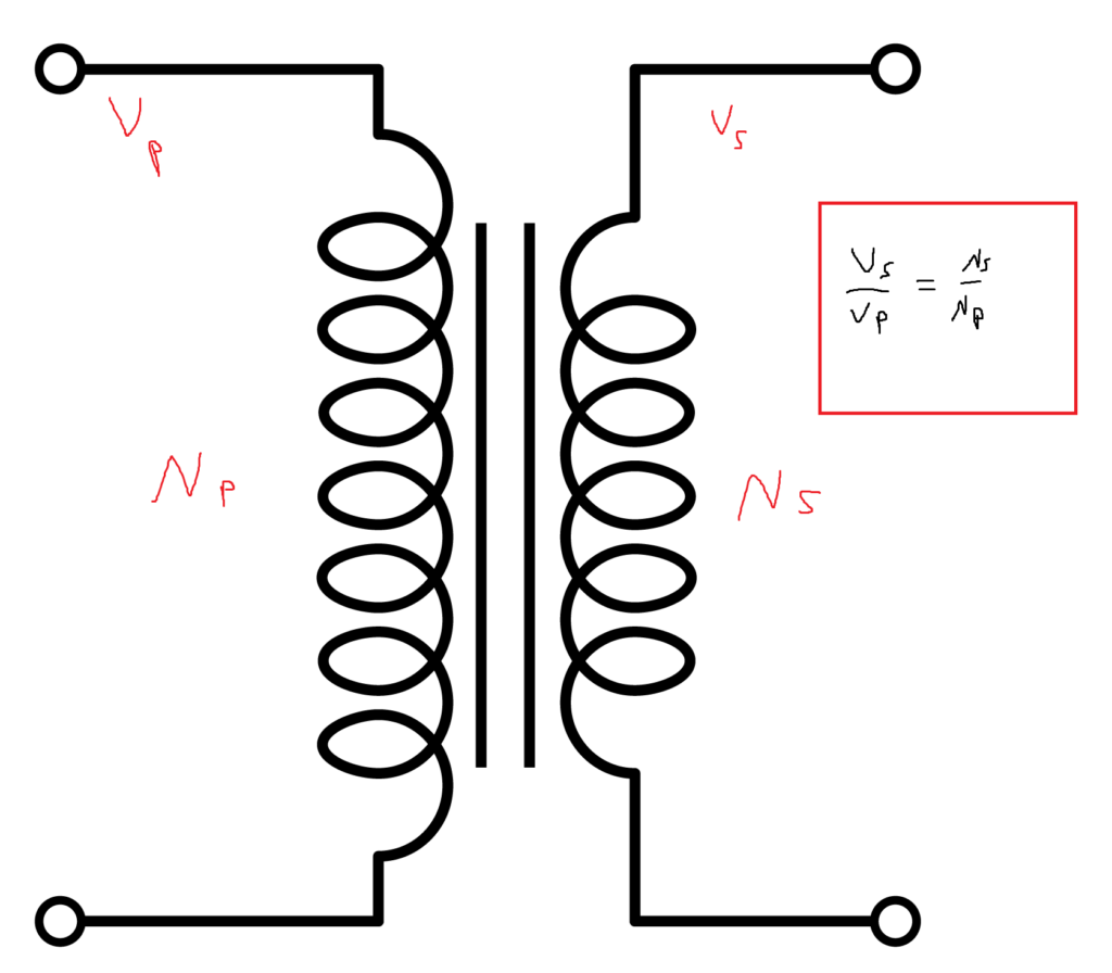
Due to how the electrical current is transferred across the inductors, it relies mainly on the ratio between the number of loops in the wires (assuming everything else is constant). If the inductor with the original AC current has more curls than the second inductor, then the current will go up since the magnetic field is changing faster. If there are fewer loops in the first inductor, then the second inductor will receive less current.
An important note is that the current isn’t the only thing that is changing. We know that power is equal to P=IV. If current went up, then power would go up. We know that energy can neither be created nor destroyed so power must be the same in both inductors. That means if current increases by a factor of two, then voltage must decrease by a factor of two in order to maintain power. The conservation of power leads us to the following continuity equation:
On a side note, induced current is also how wireless charging works.
Maxwell’s Equations
Maxwell collected all the necessary equations required to explain electromagnetic interaction and revised them. He expressed four different fundamental equations with great mathematical rigor. His equations exist in both integral and differential forms. I explain the equations using the form I thought was easier to understand.
First Equation (No Monopole Magnets)

In simple terms, Maxwell’s first equation states that there are no monopole magnets. It declares that there is no such thing as a source or sink of magnetic field lines. All magnetic fields exist in closed loops without a clear start or end. Therefore, a monopole magnet can’t exist because it would either have to be a source or a sink. Below are the magnetic field lines of a typical bar magnet. If you look closely, there is no apparent start or end to the magnetic field (since the magnetic field travels through the actual magnet as well).

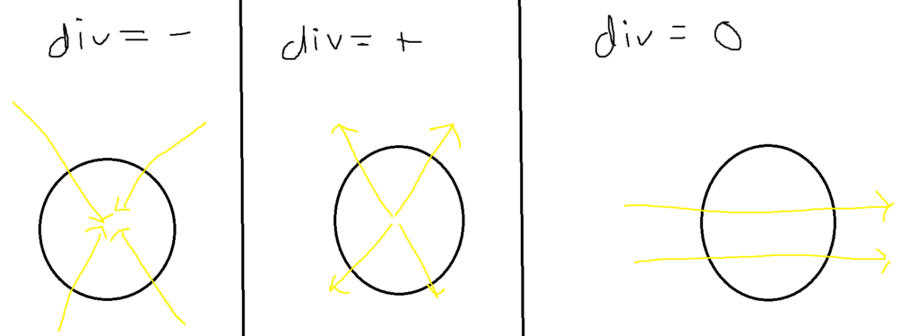
The magnetic field in the equation is represented by a vector field B. The divergence operator is then invoked on the magnetic field. The divergence of a vector field measures how much a vector field flows in or out of a certain region. A positive divergence means the field tends to flow out (from a source), and a negative divergence (from a sink) means the field tends to flow into a certain point. A zero divergence means that the field tends to just pass over the region, neither flowing in nor flowing out. In the following image, assume the circle is the region of interest for the divergence operator.
Second Equation (Induced EMF)

Maxwell’s second equation describes induced currents. If you break down the mathematics, Maxwell is saying the exact same thing as Faraday. A changing magnetic field will cause an induced current in a wire.
Let’s start with the right side of the equation. We have an integral over the surface of some object. The integral is the sum of the effects of the magnetic field at each infinitesimally small region of the object (total magnetic flux). After that, we are taking derivatives of the magnetic flux with respect to time, and we know that a changing magnetic flux is what causes induced current.
The left-hand side is a line integral over some wire with an infinitesimal arc length (dl). At each infinitesimal arc length, we are measuring the effects of the electrical field. In other words, we are calculating the total electrical current inside a loop of wire.
So, Maxwell’s second equation sets the total amount of induced current in a wire equal to the change in the magnetic field.
Third Equation (Gauss’s Law)

Similarly to magnetic flux, there is also electrical flux, which is the exact same concept but with electric fields. Gauss’s law states that the total electric flux traveling through a closed surface is equal to the total charge of the surface divided by the permittivity of free space. This is a weird one, and it’s probably best to explain it visually. Take a negatively charged particle and its corresponding electric field.
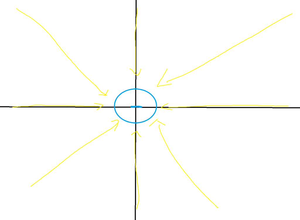
The divergence operator is applied to the electrical field. As mentioned, prior divergence measures how much a vector flows in or out of a certain area. If we draw a closed surface like a circle inside the vector field, then the divergence of the vector field at the position is proportional to the charge located in that area. Let’s say we draw a circle around point A.
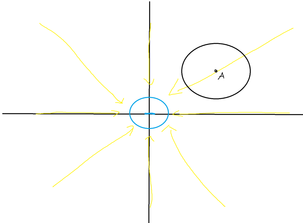
At point A, we have a divergence of zero since all electrical field lines pass through the circle (no flow in or flow out). That agrees with our claim since there is no electrical charge within the circle. The only charge in this system is located in the middle. If we draw a circle around the middle charge, we get the following:
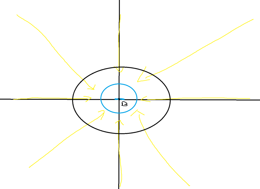
In this scenario, we will get a negative divergence since electrical field lines flow into the region and don’t flow out (we have a sink). This scenario also agrees with our claim. Inside the closed region, we have a net negative charge due to the negatively charged particle at its center. Divergence is negative, and we know that charge is negative.
Fourth Equation (Ampere’s Law)

Maxwell added on to Ampere’s original claim that the total strength of a magnetic field is proportional to the current it encloses. The left hand side of the equation and the first term on the right hand side are the exact same as before (refer back to Ampere’s Law and the circular magnetic field example).
I’m too tired to explain this right now (plus the people answering this actual know what they are talking about ), but the reason why the displacement current is needed is the following (I did not contribute to this post)