Eletrical Charge
Static electricity occurs when an object possesses a non-zero charge, which is determined by the balance between its protons and electrons. Protons are assigned a positive charge of +1, while electrons carry a negative charge of -1. As protons typically remain constant (as changing protons would result in a different element), the number of electrons primarily determines the overall charge of an object. An excess of electrons results in a net negative charge, while a deficit of electrons leads to a net positive charge. Charged objects tend to seek equilibrium, where their net charge is neutral (0).
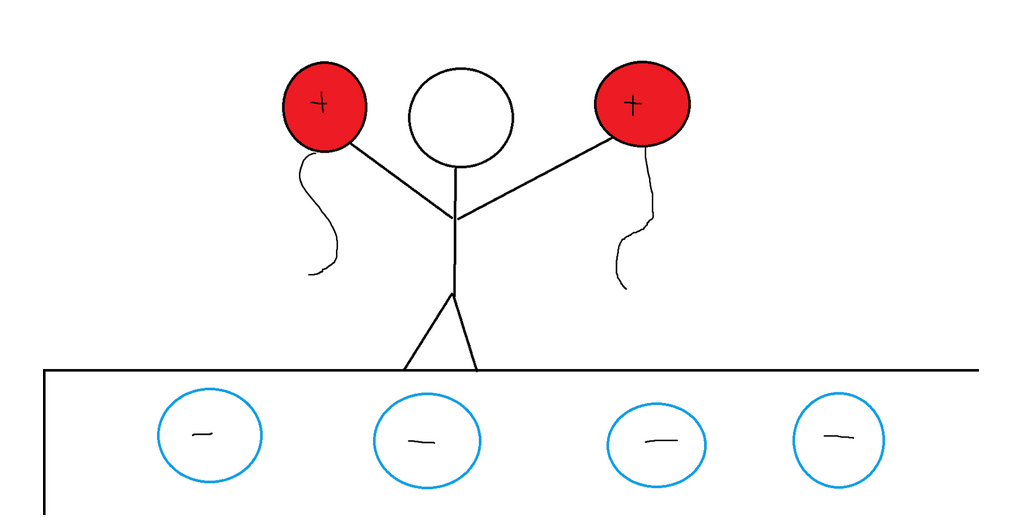
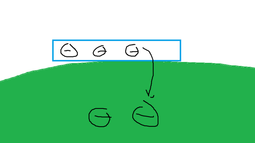
On a macroscale level, objects can be charged through friction. For instance, rubbing two balloons against a carpet causes electrons to be transferred from the surface of the balloons to the carpet. As a result, each balloon acquires a net positive charge. As you may already know, opposite charges attract while like charges repel. Consequently, the two charged balloons will repel each other when brought together. Meanwhile, the carpet obtains a net negative charge due to the extra electrons it received from the balloons. This leads to an attraction between both balloons and the carpet.
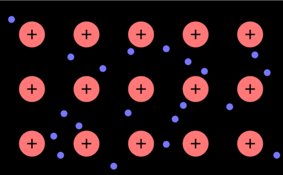
Valence electrons, located in the outermost shell of an atom, are often
referred to as free electrons because they have the ability to move
around. This mobility of electrons is what enables the conduction of
electricity. Materials that function as conductors, such as copper,
possess delocalized electron shells, which facilitate the movement of
free electrons. In contrast, insulators like solid table salt prevent
electron movement due to their lattice structure, thereby inhibiting the
conduction of electricity.
Law of conservation of Electric Charge
The principle of charge conservation states that electrical charge is always conserved. Charge can only be transferred from one object to another. If one object becomes negatively charged, another object must become positively charged to maintain overall charge balance.
Contact is another method through which particles can become charged. When two objects come into contact, electrons can be transferred between them, and the system will strive to reach a state of neutrality by redistributing the charge between the objects.
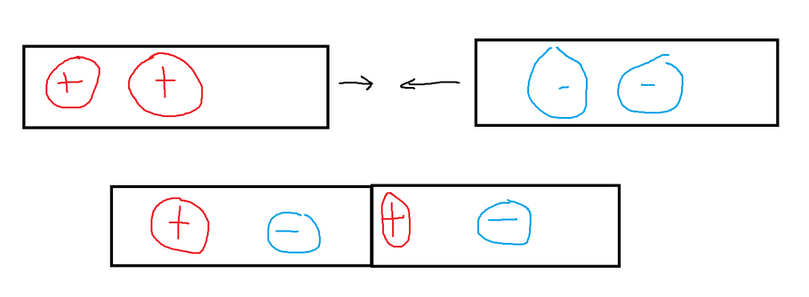
Objects can also exhibit polarization, where one side of the object carries a net positive charge, while the other side has a net negative charge. This occurs when an external electric field is applied to the object, causing the separation of positive and negative charges. Refer to the provided image.

The electrons are attracted to the positively charged object, so the left side has a built-up electron density, giving it a net negative charge. Due to the movement of the electrons to the left, there is now a lack of electrons on the right, giving it a net positive charge. Even though the composition of electrons changes, the charge of either object will not change until electrons are allowed to move between them. If you cut the bar in half while it is polarized, you will create one negative and one positive bar (charging by induction).
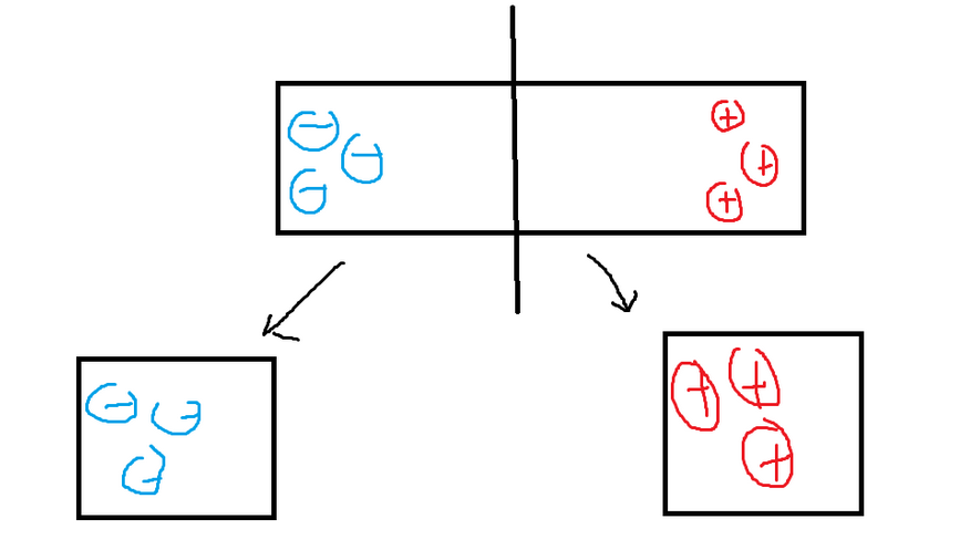
If we assume that the Earth is a neutral object, then if we take any negatively charged object, the electrons will start to transfer until both become neutral (the earth does not incur a positive charge because it is so big). The process is called “grounding”.
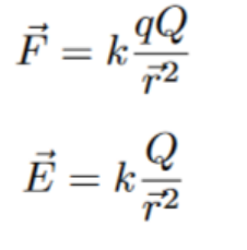
The equation to calculate the force between two charged particles is similar to the equation for gravity. Both the force of gravity and the electrostatic force (described by Coulomb’s Law) depend on the distance between the particles squared. Coulomb’s Law can be expressed as:
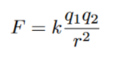
The value of the constant “k” depends on the medium through which the electrostatic force is acting. In the case of charged particles existing in a vacuum, “k” is equal to Coulomb’s constant, which incorporates the permittivity of free space. Here is the value of “k” for a vacuum:

Since the particles can be either negative or positive, the coulombic force felt between two particles can also be either negative or positive. A positive force means that they repel, and a negative force means that they attract.
Electric Fields
Coulomb’s law explains the interactions between separate charged particles. The idea of electric field lines extends Coulomb’s law.
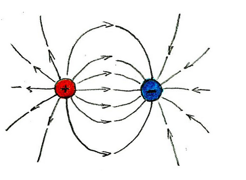
Every charged object in the universe creates an electric field, which exerts an electric force on other charged objects within its vicinity. The strength of the electric field is determined by the force experienced by a 1 coulomb test charge placed in the field. The unit of measurement for electric field strength is Newtons per Coulomb (N/C).
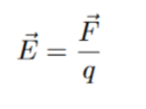
The Coulombic force is in the numerator of the equation. By substituting the appropriate expression for the force using Coulomb’s equation, the two test charges will cancel out, resulting in the following expression:
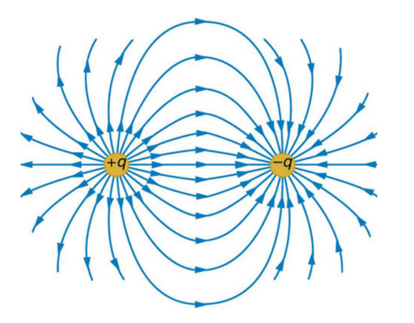
Electrical field lines are often used to depict the electric field of a charged particle. These lines originate from positively charged objects and terminate at negatively charged objects. It is important to note that electric field lines should never cross. Crossing of electric field lines would imply that the electric field acts in two different directions at the same point, which is not possible.
Superposition
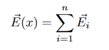
In a system with multiple charged objects, the total electric field is determined by the sum of the electric fields generated by each individual object. In other words, electric fields have the property of being able to be superimposed, meaning they can be added together to obtain the net electric field at any given point in the system.
Eletrical Field From Objects
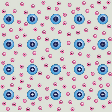
Contrary to their name, negatively charged conductors do not create a net electric field. This is because conductors, particularly metals, have a delocalized electron shell. The electrons in a conductor are free to move around and typically position themselves as far apart from each other as possible, minimizing their potential energy. As a result, the net electric field inside a negatively charged conductor is essentially zero.
If a negative electric field is applied to a negatively charged conductor, the electrons within the conductor will experience a force opposite to the direction of the electric field lines. This is because charges of the same sign repel each other. Over time, the electrons will begin to migrate towards one side of the conductor, specifically the side farthest away from the origin of the electric field. On the other hand, the protons in the conductor, being positively charged, will be attracted towards the side closer to the origin of the electric field. As a result, the charge distribution within the conductor will become uneven, with an accumulation of electrons on one side and a corresponding accumulation of protons on the other side.
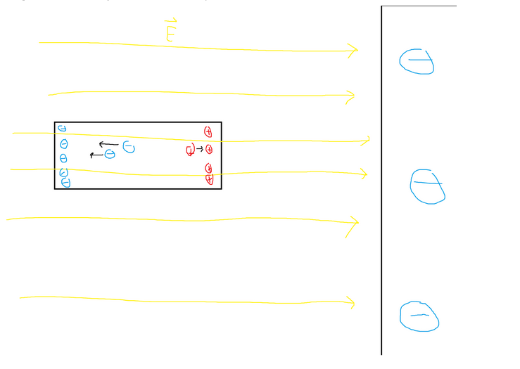
The polarization of an object gives rise to its own internal electric field, which extends from the positively charged side to the negatively charged side. This new electric field (E2) always opposes the direction of the original electric field (E1). Electrons within the object will continue to move until the magnitude of E1 becomes equal to the magnitude of E2. Both electric fields have the same magnitude but point in opposite directions, resulting in no net electric field within the object. As a result, the interior of the object experiences no overall electric field.
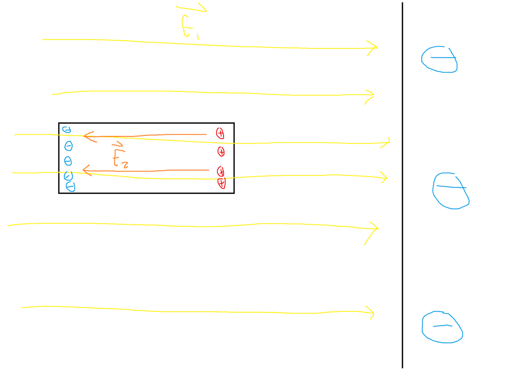
Conductors exhibit the property of creating an equal and opposite electric field to cancel out any external electric field, regardless of their shape. While there may be no electric fields present within the conductors themselves, electric field lines can still exist on their surfaces. These surface electric field lines indicate the distribution of charges and the response of the conductor to external electric fields.
Voltage, Eletricity, and the Capacitor
In the scenario of two charged plates separated by a distance, with one plate positively charged and the other plate negatively charged, there exists an electric field between them. This electric field extends from the positive plate towards the negative plate.
If a positive test particle is placed in between the plates, it will experience a force due to the electric field. The direction of this force will be in the direction of the electric field lines, which is from the positive plate towards the negative plate. As a result, the positive test particle will be attracted towards the negatively charged plate and move in that direction under the influence of the electric field.
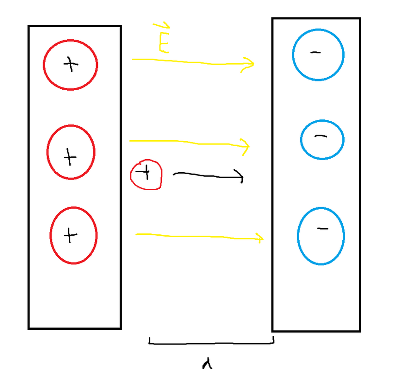
We can calculate the work done by the electric field on the test particle using the formula for work, which is equal to force multiplied by distance. By substituting Coulomb’s law into the expression for force and substituting the magnitude of the electric field, we can obtain the following expression:
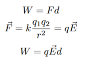
Electrical potential is defined as the change in potential energy over some arbitrary test charge. Also from classical mechanics we know that the change in potential energy is equal to negative work.
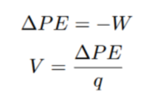
Plugging in all of the values we get the following equation:
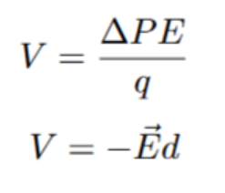
Electric potential is a measurement in volts (V) and represents the amount of work required to move a unit positive charge from infinity to a specific point. It is measured in joules per coulomb (J/C), which signifies the amount of energy needed to move one coulomb of charge.
It’s important to distinguish between electric potential and electric potential energy. Electric potential energy refers to the energy stored in an object due to its electric potential. When a charged object is held within an electric field, it possesses electric potential energy. Once released, this potential energy can be converted into kinetic energy.
In electrical field diagrams, equipotential lines are depicted as lines that indicate locations of constant voltage. In the case of two plates, the equipotential lines may appear as follows:
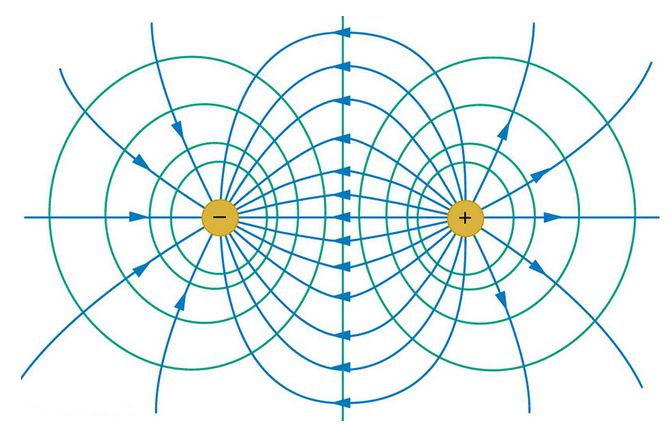
In the diagram, the blue lines represent electric field lines, while the green lines represent equipotential lines. The spacing of the circles in the inward direction becomes denser because of the behavior of electric fields. The strength of the electric field is proportional to the SQUARE of the distance. As a result, a particle situated very close to one of the charged objects can compensate for the distance from the other charged particle, as the force between them increases rapidly with proximity.
Furthermore, the equipotential lines that are farther away represent lower voltages. This is because the potential difference decreases with increasing distance from the charged objects.
The equipotential lines for a particle between two charged plates goes as follows:
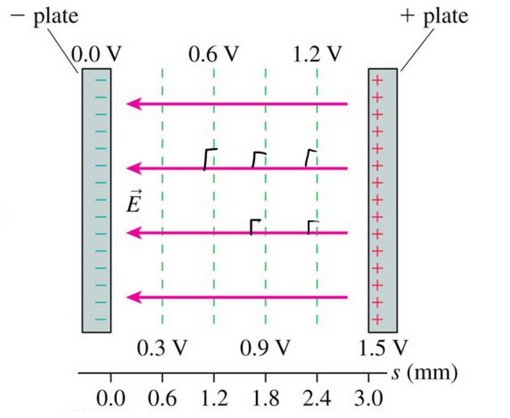
The parallel charged plate example, also known as a capacitor, is not only a useful illustration of an electric field but also a fundamental component in electronic devices. Capacitors are used to temporarily store electrical charge.
When a battery is connected between the two plates of a capacitor, electrons flow from one plate to the other, resulting in an abundance of electrons (negative charge) on one side and a deficiency of electrons (positive charge) on the other side.
If the battery is disconnected and the capacitor is connected to a light, the electrons on the negatively charged plate will begin to migrate towards the other plate, passing through the light and causing it to turn on. This process continues until both sides of the capacitor become neutral, and there is no further incentive for electrons to move.
The presence of a gap between the two plates is crucial for capacitors. Without this gap, there would be no path for electrons to travel through the circuit with the light. In fact, the capacitor would not become charged at all.
The strength of a capacitor, measured in farads (F), indicates its capacitance. The SI unit for farads is coulomb per volt (C/V), which can be mathematically expressed as follows:
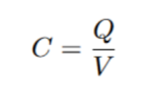
The area of each plate will impact the capacitance. If you make the plates bigger, there is more room for electrons(hopefully this is pretty intuitive). If you move the two plates closer together (without allowing electrons to jump across), then capacitance will also go up. In the denominator, the formula for capacitance has electric potential energy, which is proportional to distance. Substituting some of this information, we get the following (currently assuming they are separated by a vacuum):
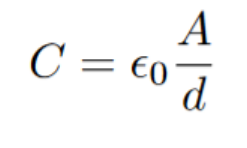
Sticking objects between the plates also increases capacitance. The objects are called dielectrics. Although there is a gap between the capacitor plates, it is still possible for electrons to jump across (as temperature increases, this becomes more common). A dielectric is put between the plates to minimize the transfer of charges over the gap. That allows you to move the plates closer without risking the functionality of the capacitor. In order to negate rather than expedite charge movement, we ujse insulators (plastic, glass, etc.), which are don’t readily allow electron movement.
The electrical field caused by the charged plates has an impact on the structure of the dielectric. The dielectric will become polarized. One side of the dielectric will become negatively charged (attracted to the positive capacitor plate), and other side will become positively charged (attracted to the negative capacitor plate). Now that the dielectric is polarized, an electrical field will be created inside it (almost like another charged plate system). This causes an overall weaker field, making it even less likely for electrons to make it between the two capacitor plates.
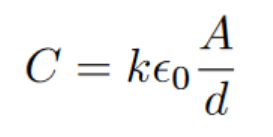
The dielectric constant will vary depending on the material. We represent it by adding another constant factor to the capacitor equation (dielectric constants are obtained experimentally, and the dielectric of air happens to be basically one, hence why it could be omitted earlier):
Electric potential energy is stored in the electric field between the plates. In order to find the total potential energy between the plates, we can integrate the voltage over the charge of one of the plates. The derivation of the potential energy equation goes as follows:
Work is equal to charge divided by capacitance integrated with respect to charge. You can work out that the unit q/C is equivalent to newtons, and that integrating over various charges will give force times distance.
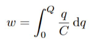
Integrating we get the following:
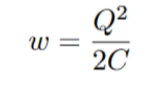
Separating this equation a little, we find out that we have a Q/C factor, which is equivalent to voltage. We also know that the change in potential energy equals work, so the final equation is the following:

Eletric Current
Electricity flows in a very similar manner to water or any other Newtonian fluid. Electrical current is the total amount of charge that passes through an area over a period of time.
Charge will always move from an area of high voltage to one of low voltage. A bigger voltage difference is what will cause a faster electrical current. Many people choose to draw similarities between voltage and current and the pressure and flow of water.
We don’t live in an ideal world, so there will be objects that resist the flow of electrical charge. Resistance is measured in ohms. A resistance of one ohm will allow a 1V source to produce 1A of current. Everything has resistance, even the wires that carry the current. Engineers use resistors to control the current. Many people relate resistance to the size of the pipe the fluid might flow through. Small pipe means high resistance as not much water is let through. Refer to the full water analogy below:

All three of these properties are related to each other through Ohm’s law, which is as follows:

Materials will have varying amounts of resistance. Conductors like copper have very little resistance, while insulators like wood have high resistance.
As the current flows through any resistance, it will lose energy. The energy that was lost is then turned into another form of energy, usally in the form of heat or light. When you pass a current through a lightbulb, it will apply resistance, allowing the electrical energy to transform into light. However, some heat energy will also be produced, which is why lightbulbs get hot if they have been left on for a while.