What is AES?
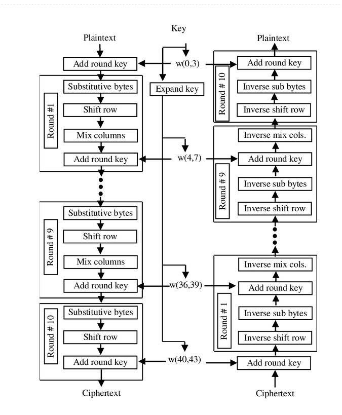
AES (Advanced Encryption Standard) is the standard for most current encryption protocols. It builds upon the concept of SP networks. Like other encryption algorithms, AES aims to make it difficult to obtain the plaintext without access to the key. It achieves this by employing alternative methods of storing information, substituting bits, permutating data, and integrating the key into each of these steps.
SP-Networks:
AES is built on the idea of SP networks. SP networks are simpler but still accomplish the task of generating a ciphertext. They take a string of bits as input and break them into smaller chunks. Inside SP networks, there are two operations: substitution (the “S” in SP) and permutation (the “P” in SP). The substitution layer is a mapping operation. A predetermined table is used to determine the values to be substituted. For example, if a 4 is passed in, it might be mapped to 5, and if a 6 is passed in, it might be mapped to 4. Refer to the following 3-bit example.
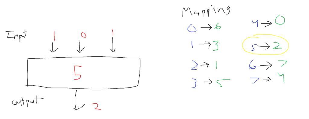
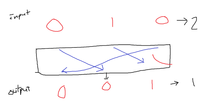
This obviously is very strong on its own. However, if the mapping gets leaked then the entire cipher would be useless. When it comes to mapping, there are indeed better mappings than others. After the substitution operation, the data is then passed to a permutation box that contains pre-determined swaps. For instance, index 0 is moved to index 1, index 1 is moved to index 2, and index 2 is moved to index 0. Following the permutation, a new output is generated that is a permutation of the input. For an example of this operation refer below:
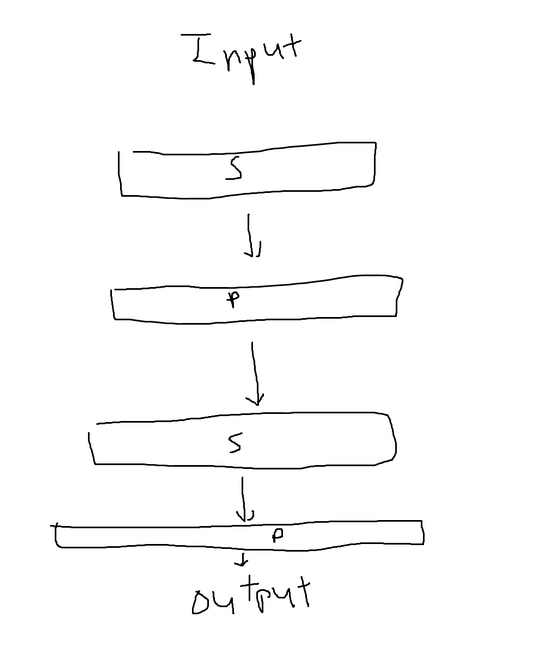
The substitution boxes and permutation boxes are combined in an alternating system, forming a network similar to the one depicted below. The output of one box is used as the input to the next box. Each combination of a substitution (S) and permutation (P) is referred to as one round. In the provided image, there are two rounds illustrated. The security of the system increases with more rounds, but it also results in longer processing times. It’s worth noting that encryption methods typically do not rely solely on basic SP networks. However, AES, which is based on the concept of SP networks, employs 10, 12, or 14 rounds as the standard.
SP networks can also be more complex than the simple representation mentioned earlier. In the provided image, the input is divided into two halves, and each half undergoes a separate S box with different mappings. The outputs of the S boxes are then combined using a permutation box, which can be achieved by reversing the permutation mappings and reversing the mappings in the S boxes. This allows for a more intricate transformation of the data within the SP network.
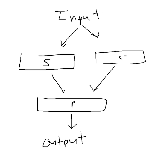
However, an issue still persists. If the information for the all the S
boxes and all the P boxes is exposed then anyone can decrypt the
message. We need to make use of a key throughout the process to fix this issue. A
key will be generated and split into the number of rounds plus one.
After each round, the key will be XORed with the output before
continuing to the next. As long as the key is concealed, it doesn’t
matter how much information is known about the system; it still remains
extremely hard to crack.

Decrypting isn’t particularly difficult when the key is available. The process involves reversing the substitution and permutation mappings. For instance, if the substitution transformed a 3 into a 2, reversing the substitution would convert a 2 back into a 3. To decrypt, one would start from the bottom of the network and work their way back up, effectively inverting the encryption. The reversal applies to the substitution and permutation boxes throughout the process. The XOR operation is its own inverse, so it remains unchanged during decryption. Refer to the image below:

AES Algorithim
AES follows a similar system to SP networks, although with a slight variation. In an SP network, the input is stored in a linear fashion. However, in AES, the information is organized within a two-dimensional grid. For instance, a 128-bit chunk is divided into 16-byte blocks, where each byte represents a cell in the grid. The bytes are arranged in the grid from left to right and top to bottom order.
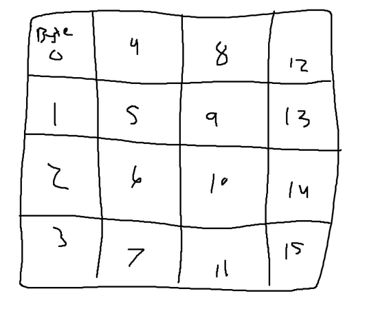
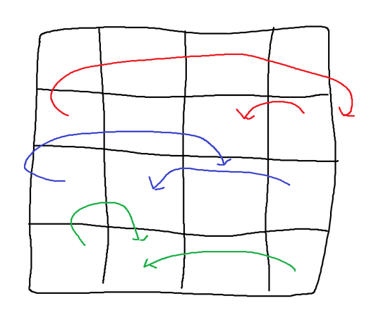
In AES, the permutation step has been divided into two parts: shifting rows and mixing columns. Shifting rows involves moving elements within each row based on the index of the row. In row 0, each element remains in place (shifted 0 times). In row 1, each element is shifted to the left once. In row n, each element is shifted to the left n times. It’s important to note that each row is considered circular, meaning that the start of the row is linked to the end of the array.
For example, if the algorithm is at index 0 in row 2, it will move the value to the end of the array, and then to the element before the last one. This shifting operation applies to every cell, but the provided image only shows the general and circular cases for demonstration purposes.
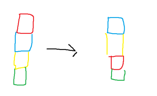
Now let’s discuss the mixing of columns. In AES, each column’s cells are rearranged using matrix multiplication. The process described below applies to each individual column, and it would be repeated for every column. If we continue with the current example, it would run four times in total.
Once again, if the substitution mapping and mixing column matrices used in AES were revealed, the algorithm would be rendered ineffective. Therefore, the use of a key is necessary. Similar to SP networks, the key is XOR’d with the grid and added before the start of each round. Decrypting AES is relatively straightforward. Just as in SP networks, all mappings are reversed. For example, if the algorithm is currently on row 1, instead of moving everything to the left, it should be moved to the right to reconstruct the original message. The provided image illustrates the entire process in detail.
