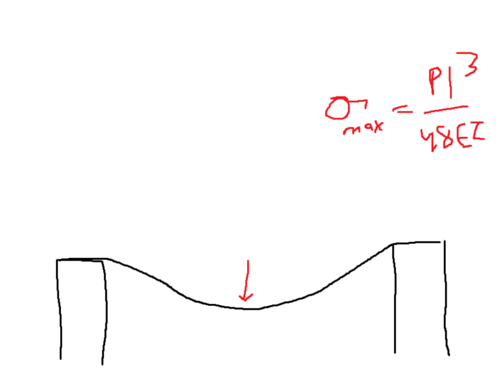
Items will bend differently depending on how they are oriented. A plank placed horizontally will bend more drastically than when it’s placed vertically.
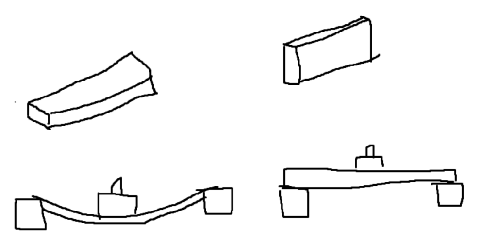
In the second orientation, there is more material between the force and where the plank will bend. If you think about it completely geometrically, this ability to resist bending is referred to as the moment of inertia.
The moment of inertia depends on where the “bending axis” is. In most scenarios, this is referring to the centroidal axis. Which are the axes that pass through the centroid (center of gravity) of the shape?
By taking the area above and below the bending axis and multiplying it by their distance squared from the axis, Refer to the following image:
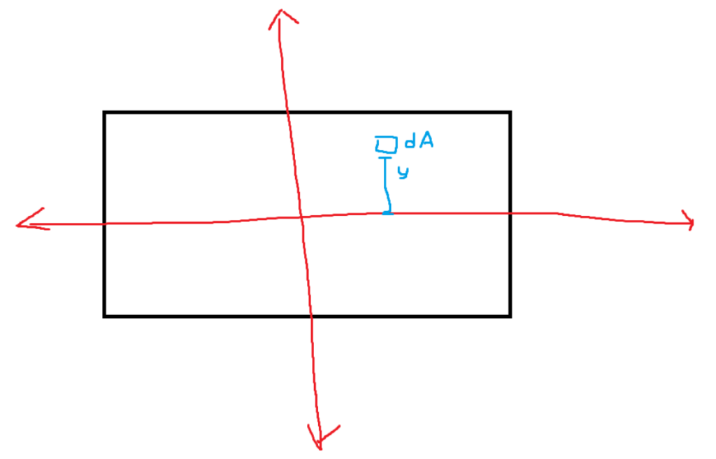
Imagine there were more squares of area dA each with a squared distance from the x-axis. If you add all of them together, you get the moment of inertia. Formulated below.
How good the estimate is depends on how small the area of each square is. If you turn the sum into an integral, then the moment of inertia can be determined with extremely high precision. Below is the integral used to determine the formula for the moment of inertia of a rectangle.
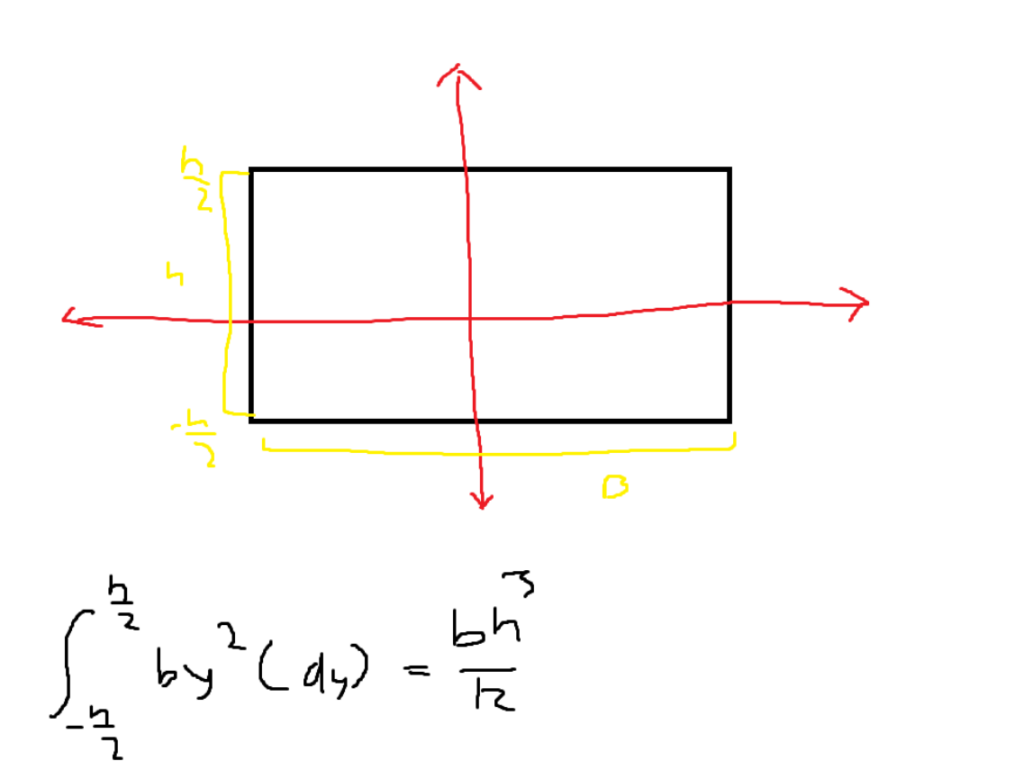
Many of the integrals for simple shapes have already been done for you. Refer to this Wikipedia page for formulas for general shapes: https://en.wikipedia.org/wiki/List_of_moments_of_inertia.
In the above problem, the height cubed is multiplied by the base. If both of these values were distances, we would end up with distance to the fourth as our units. The most common units for moment of inertia are in^4 and mm^4.
Parallel Axis Theorem
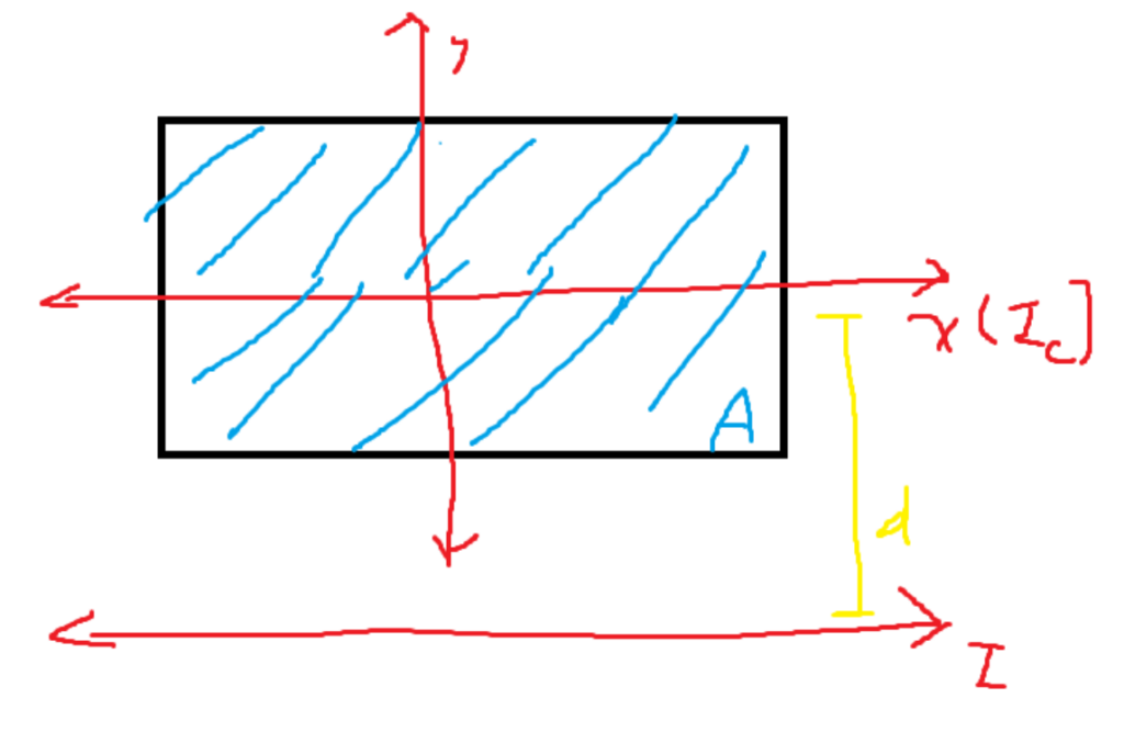
So far, we have been calculating the moment of inertia of the centroidal axis. However, there is an easy formula for finding the moment of inertia for an axis that is parallel to any of the centroidal axes. The formula goes as follows:

The new moment of inertia is equal to the moment of inertia at a centroidal axis plus the area times the squared distance.
There is another property of the moment: inertia. It can easily be subtracted and added to other moments of inertia if they both use the same reference angle. Refer to the below image, where we were tasked with finding the moment of inertia aligned with the centroidal x-axis.
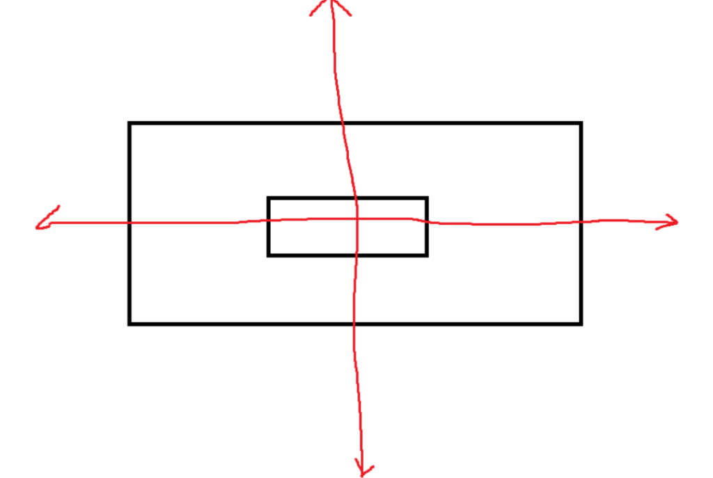
If we assume that the middle rectangle is cut out, then the moment of inertia of the shape can be found by subtracting the two. The moment of inertia of the giant rectangle is minus the moment of inertia of the small rectangle cut out.
Let’s say you try to find the moment of inertia on the blue line of the cross section of an I-beam. To do this, you broke it up into three separate parts, and you plan on summing them. However, you can’t simply add all of the moments of inertia together because they aren’t all referencing the same reference axis. If you are using the formula, it will give you the moment of inertia along a centroidal axis. For the horizontal centroidal access, each part has a different axis. Refer to the image.
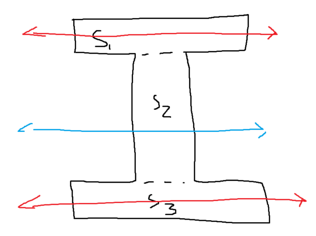
This is where the parallel axis theorem is helpful. First, we could use a simple formula to calculate the moment of inertia for S1 and S3 along their horizontal centroidal axes. Then, using those values, we can use the parallel axis theorem to “move” them to the blue axis, which is what we are trying to analyze. Since S2’s horizontal centroidal axis already seems in place, just calculate the moment of inertia there. We currently have all three moments of inertia with a reference axis of the blue line. We can just sum them up to get the total moment of inertia for the I-Beam.
Polar Moment of Inertia (J):
In the previous examples, we were always calculating using a reference angle that was parallel to either the x-axis or the y-axis. However, it’s also important to be able to calculate a value perpendicular to the cross section.
It can be calculated the same way. Instead of having a perpendicular line to an axis, define its distance. A potentially diagonal line might need to be used to measure the total distance to the reference axis. Refer to the following image:
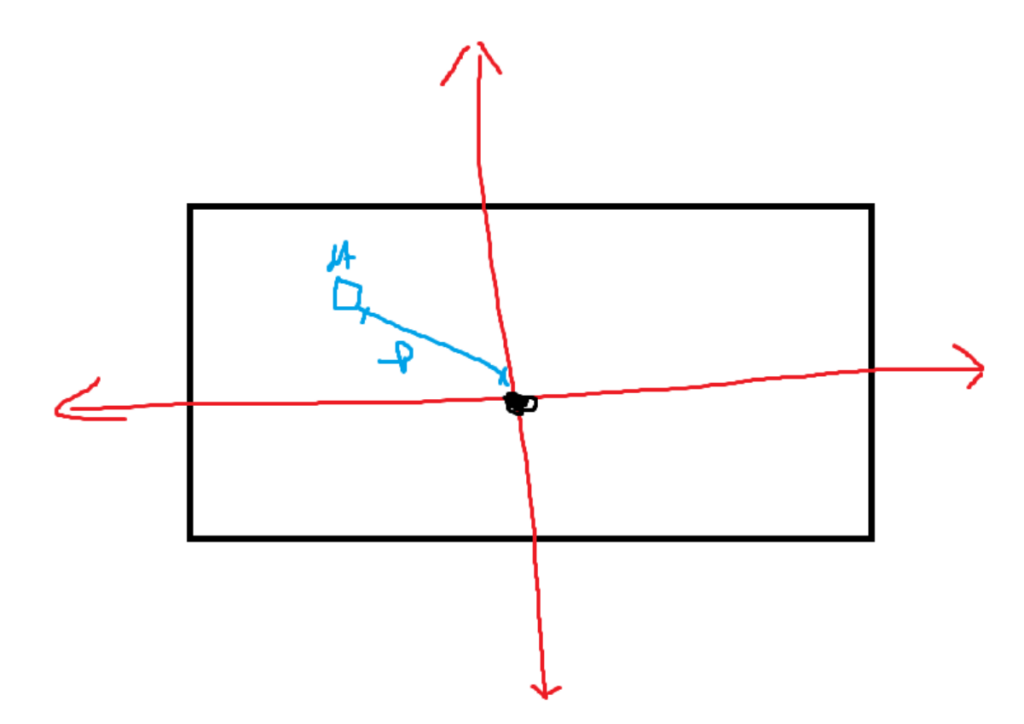
The polar moment of inertia is used to calculate how well an object can resist a turning motion along the reference axis.
Description of an Application:
The moment of inertia is key for constructing buildings. In many formulas involving the deflection of a beam (how much it bends when there’s force on it), they usually all include E * I. Where E is the elastic modulus and I is the moment of inertia. The moment of inertia gives its geometric resistance to bending, and the elastic modulus deals with the material’s property. Multiplied together, they fully describe something’s ability to resist bending.
